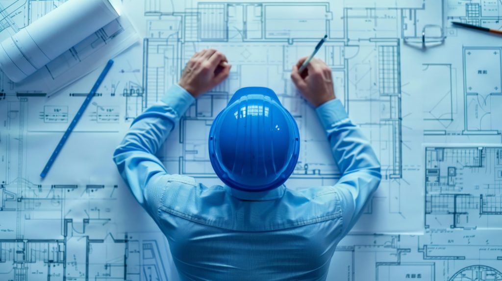
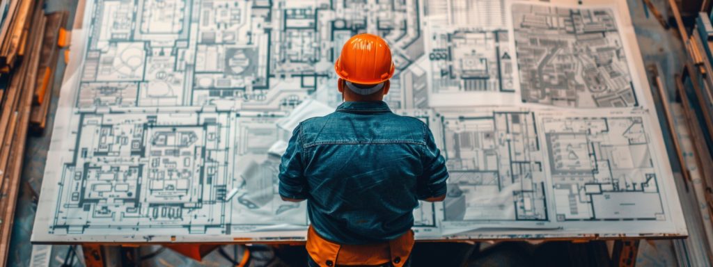
On a construction site, all the construction execution is done on the basis of pre-planned drawings provided by structural engineers and architects. In construction, having a comprehensive set of drawings is essential for transforming plans into a completed project. Each drawing type plays a specific role, from laying out the initial design to detailing the components that maintain safety, compliance, and functionality. This blogpost enlist the different types of drawings and highlights the main types of drawings needed for construction, explaining how each contributes to a well-organized, efficient building process.
Types of Drawings Required for Construction

1. Architectural Drawings
Architectural drawings provide the foundation for any construction project, outlining the layout, design, and structural appearance. They give builders and contractors a visual reference, helping them maintain consistency with the overall plan.
- Floor Plans: Show the layout of each floor, marking walls, windows, doors, and other structural elements.
- Elevations: Provide a side view, showing building height and external details.
- Sections: Display cross-sectional views, showing structural details and interior layout.
Purpose: To offer a comprehensive view of the building’s design for accurate execution on site.
2. Structural Drawings
Structural drawings guide the construction of the building’s framework, including beams, columns, and foundations, ensuring that every component supports the required loads and stands firm.
- Foundation Plans: Describe the type and depth of the foundation for load-bearing.
- Framing Plans: Show the configuration of structural elements, such as beams and girders.
- Reinforcement Details: Indicate the placement of steel bars in concrete to strengthen the structure.
Purpose: To create a stable framework that safely distributes weight and stress across the building.
3. Electrical Drawings
Electrical drawings are essential for distributing power throughout the building. They outline the location of outlets, switches, and fixtures, helping electricians work effectively while reducing risks of electrical issues.
- Lighting Layouts: Show the placement of lighting fixtures and control points.
- Power Layouts: Map out outlets, circuits, and switchboards.
- Cable Routes: Guide the installation of primary and secondary cables for efficient wiring.
Purpose: To provide a clear layout for power distribution, allowing safe and efficient electrical installations.
4. Plumbing and Sanitary Drawings
Plumbing and sanitary drawings cover water supply and drainage systems, ensuring that the building’s needs for clean water, waste disposal, and ventilation are met efficiently.
- Water Supply Layouts: Show the distribution of water sources throughout the building.
- Drainage Layouts: Outline waste and stormwater disposal routes.
- Fixture Details: Provide specifications for sinks, toilets, and pipe systems.
Purpose: To help plumbers establish a reliable water and waste management system.
5. HVAC Drawings
HVAC drawings are critical for laying out heating, ventilation, and air conditioning systems. They show where ducts, units, and vents will be installed to regulate temperature and airflow.
- Duct Layouts: Detail the placement of air ducts for ventilation.
- Heating & Cooling Plans: Show where heating and cooling units will be installed.
- Ventilation Plans: Ensure proper air circulation and indoor air quality.
Purpose: To help HVAC specialists implement systems that maintain comfortable temperatures and air quality.
6. Fire and Life Safety Drawings
Fire and life safety drawings ensure that the building meets safety standards. These plans include emergency exits, alarms, and fire equipment, designed to protect occupants in case of an emergency.
- Exit Plans: Show locations of emergency exits and escape routes.
- Fire Equipment Layouts: Mark spots for fire extinguishers and hydrants.
- Alarm System Details: Map out fire and smoke alarm placements.
Purpose: To help meet safety standards and enable quick responses during emergencies.
7. Finishing and Interior Drawings
These drawings focus on the final touches, covering finishes, furnishings, and fixtures. They ensure that each area looks and functions as intended once construction is complete.
- Ceiling Plans: Specify ceiling designs and materials.
- Floor Finishes: Detail types of flooring and installation guidelines.
- Furniture Layouts: Suggest placements for furniture to optimize space.
Purpose: To ensure that the interior is completed to the required design and functional specifications.
8. Landscape Drawings
Landscape drawings cover outdoor spaces, detailing gardens, pathways, and exterior facilities. They guide the creation of attractive, functional outdoor environments.
- Plant Layouts: Indicate the placement and types of plants.
- Hardscape Plans: Show pathways, pavements, and other exterior features.
- Irrigation Plans: Outline water systems for maintaining green areas.
Purpose: To provide a blueprint for designing practical, visually appealing outdoor areas.
9. Shop Drawings
Shop drawings offer a closer look at the assembly of complex building components like windows, doors, and cabinetry. Typically created by contractors, these drawings show the dimensions and installation process for each item.
- Detailed Dimensions: Include precise measurements for each component.
- Assembly Instructions: Provide guidelines for accurate installation.
- Material Specifications: Describe material choices and finishes.
Purpose: To ensure complex components are accurately fabricated and installed.
10. As-Built Drawings
As-built drawings record any changes made during construction, showing the final state of the project. They’re helpful for future maintenance, renovations, or repairs.
- Accurate Layouts: Show the completed floor plan with modifications.
- Utility Locations: Mark exact positions of plumbing, electrical, and HVAC systems.
- Structural Changes: Document adjustments to the original design.
Purpose: To provide an exact record of the final building for future reference.
Quick Reference Table: Types of Construction Drawings

| Drawing Type | Purpose | Key Features |
| Architectural Drawings | Guide overall design and layout | Floor plans, elevations, sections |
| Structural Drawings | Ensure load-bearing and stability | Foundation, framing, reinforcement details |
| Electrical Drawings | Guide power distribution | Lighting layouts, power plans, cable routes |
| Plumbing & Sanitary | Outline water supply and drainage systems | Water layouts, drainage, fixture details |
| HVAC Drawings | Maintain climate control | Duct layouts, ventilation plans |
| Fire & Life Safety | Protect occupants in emergencies | Exit routes, alarm systems |
| Finishing & Interior | Detail interior aesthetics and functionality | Ceiling, flooring, furniture layouts |
| Landscape Drawings | Plan outdoor areas | Plant layouts, hardscape, irrigation plans |
| Shop Drawings | Ensure assembly of complex parts | Detailed measurements, assembly instructions |
| As-Built Drawings | Record completed structure with changes | Layouts, utility locations, structural updates |
Read More:- 7 Different Types of Architecture You Should Know About
Conclusion
Every construction drawing type serves a specific purpose in guiding the building process from design to completion. By adhering to these detailed plans, teams can avoid costly mistakes and deliver a structure that aligns with both practical and aesthetic expectations.
Let every line lead to a structure that stands the test of time.

